Saturday, September 12, 2009

Boiling & Freezing Temperature of Components in Natural Gas

Natural gas contains component such as Methane, Ethane, Propone, and other inert gas. Following table list the Boiling and Freezing temperature at ATM which is sometime useful.

COMPONENT
Abbr.
Boiling
Temperature
(degC)
Freezing
Temperature
(degC)
Helium He
- 268.6
Hydrogen H2
- 252.5
Nitrogen N2
- 195.8 - 209.9
Methane C1
- 164.0
Carbon Dioxide CO2
- 78.5
Freon 12 Freon-12
- 29.8
Water
H2O
0.0


Other Interesting Article

Saturday, August 29, 2009

Flammability Limits

Flammability Limits

Lower flammable limit (LFL) or Lower Explosive Limit (LEL) is minimum vapor concentration in air which a mixture will burn when an ignition source is present.

Upper flammable limit (UFL) or Upper Explosive Limit (UEL) is maximum vapor concentration in air which a mixture will burn when an ignition source is present.

Concentration of mixture of vapor in air below LFL/LEL (too lean) or above UFL/UEL (too rich), mixture will not burn even an ignition source is present. Therefore, flammable range or explosive range is concentrations between LFL/UFL and UFL/UEL.

LFL/LEL and UFL/UEL for some common gases are indicated in table below. Some of the gases are commonly used as fuel in combustion processes.

Fuel Gas (LFL/LEL)
(%)
(UEL/UFL)
(%)
Acetaldehyde 4 60
Acetone 2.6 12.8
Acetylene 2.5 81
Ammonia 15 28
Arsine 5.1 78
Benzene 1.35 6.65
n-Butane 1.86 8.41
iso-Butane 1.80 8.44
iso-Butene 1.8 9.0
Butylene 1.98 9.65
Carbon Disulfide 1.3 50
Carbon Monoxide 12 75
Cyclohexane 1.3 8
Cyclopropane 2.4 10.4
Dimethyl Ether3.4
27
Diethyl Ether 1.9 36
Ethane 3 12.4
Ethylene 2.75 28.6
Ethylene Oxide
3.6
100
Ethyl Alcohol 3.3 19
Ethyl Chloride 3.8 15.4
Fuel Oil No.1 0.7 5
Hydrogen 4 75
Isobutane 1.8 9.6
Isopropyl Alcohol 2 12
Gasoline 1.4 7.6
Kerosine 0.7 5
Methane 5 15
Methyl Alcohol 6.7 36
Methyl Chloride 10.7 17.4
Methyl Ethyl Ketone 1.8 10
Naphthalene 0.9 5.9
n-Heptane 1.0 6.0
n-Hexane 1.25 7.0
n-Pentene 1.65 7.7
Neopentane 1.38 7.22
Neohexane 1.19 7.58
n-Octane 0.95 3.20
iso-Octane 0.79 5.94
n-Pentane 1.4 7.8
iso-Pentane 1.32 9.16
Propane 2.1 10.1
Propylene 2.0 11.1
Silane 1.5 98
Styrene 1.1 6.1
Toluene 1.27 6.75
Triptane 1.08 6.69
p-Xylene 1.0 6.0

Note : The limits indicated are for component and air at 20oC and atmospheric pressure.

Others Interesting Articles

Friday, August 28, 2009

Minimum Oxygen Concentration (MOC)

Standard air composition is the bulk average air composition encountered at or around sea level. Typically it contains the following composition.

Component
Abbr.
%Wt
%Vol.
MW
Nitrogen N2
75.4778.0828.01
Oxygen O2
23.2020.9532.00
Carbon Dioxide
CO2
0.05900.03844.01
Hydrogen
H2
0
0.00005
2.02
Argon
Ar
1.280.93
39.95
Neon
Ne
0.00120.0018 20.18
Helium
He
0.00007 0.00054.00
Krypton
Kr
0.00030.0001
83.80
Xenon
Xe
0.00004 8.7x10^-6131.30


From standard air composition at sea level, the oxygen content is approximately 20.95% by volume. Oxygen is the main component in fire triangle in generating of fire. From chemistry, without any one of the element, a fire will NOT form.


Although Oxygen is the major component in generating fire, there is still a minimum oxygen concentration (MOC) required present combustible mixture so that a fire can be initiated. Below this limit, a fire will not form. Base on this principle, hydrocarbon mixture is purge with inert gas such as Nitrogen, Carbon dioxide, etc so that the MOC is not reach and therefore combustible mixture is not form.

Common unit used for MOC is % oxygen in air plus fuel. Following table listed several

Component
MOC (%O2)
Hydrogen
4.0
Acetylene
6.2
Methane (C1)
12
Ethane (C2)
11.2
Ethylene (C2=)
9.9
Propane (C3)
11.6
Propylene (C3=)
11.5
Butane (C4)
12.3
1-Butene (C4=)
11.0
Pentane (C5)
11.8
Hexane (C6)
11.8
Benzene
11.5
Methyl Alcohol
9.9
Ethyl Alcohol
10.5
Dimethyl Ether
10.5
Diethyl Ether
10.2
Methyl Acetate
11.0
Methyl Ether Ketone
11.0
Carbon Disulfide
5.0

Generally a mixtures of Hydrocarbon vapor MOC is around 10% Vol.

API STD 520 recommends MOC of 6 %Vol. for flare stack design to avoid combustible mixture present in flare system. Hydrogen rich flare gas shall consider lower MOC i.e. 3-4% vol.

Ref : "Application of Flammability Diagram For Evaluation of Fire & Explosion Hazards of Flammable Vapor", C.V. Mashuga, D.A. Crowl


Others Interesting Articles

Sunday, August 16, 2009

Conversion from MMSCFD to kg/s

How to convert MMSCFD to Kg/s ?

Standard condition (S) measure at 1.01325 bara & 15.56 degC (60 degF)
Normal condition (N) measure at 1.01325 bara & 0 degC

1.0 MMSCFD
= 1,000,000/(24 x 3600) Sft³ /s
= 1,000,000/(24 x 3600)/35.3152 Sm³/s
= 1,000,000/(24 x 3600)/35.3152 x (273.15/288.71) Nm³/s
= 1,000,000/(24 x 3600)/35.3152 x (273.15/288.71)/22.414 kmol/s
= 1 / 72.2826

1 MMSCFD = 1 / 72.2826 kmol/s

or

Saturday, June 20, 2009

Thermal Conductivity & Unit Conversion

Thermal conductivity (k) is ability of heat conduction for material. It is heat (Q) transmitted through a unit thickness (x) in a direction normal to a surface of unit area (A) with temperature difference (dT) at steady state conditions.

k = (Q/A).x / dT

Thermal conductivity Unit & Conversion

  • 1 W/(mK) = 0.85985 kcal/(hr.moC)
  • 1 W/(mK) = 0.57779 Btu/(ft.hr oF)
  • 1 W/(mK) = 6.9335 Btu.in/(ft2.hr oF)
Thermal Conductivity - k - (W/mK)
Material25oC
Acetone 0.16
Acrylic 0.2
Air 0.024
Alcohol 0.17
Aluminum 250
Aluminum Oxide 30
Ammonia 0.022
Antimony 18.5
Argon 0.016
Asbestos-cement board 0.744
Asbestos-cement sheets 0.166
Asbestos-cement 2.07
Asbestos, loosely packed 0.15
Asbestos mill board 0.14
Asphalt 0.75
Balsa 0.048
Bitumen 0.17 - 0.33
Benzene 0.16
Beryllium 218
Brass 109
Brick dense 1.31
Brick work 0.69
Cadmium 92
Carbon 1.7
Carbon dioxide 0.0146
Carbon Steel
50
Cement, portland 0.29
Cement, mortar 1.73
Chalk 0.09
Chrome Nickel Steel (18% Cr, 8 % Ni) 16.3
Clay, dry to moist 0.15 - 1.8
Clay, saturated 0.6 - 2.5
Cobalt 69
Concrete, light 0.42
Concrete, stone 1.7
Constantan 22
Copper 401
Corian (ceramic filled) 1.06
Corkboard 0.043
Cork, regranulated 0.044
Cork 0.07
Cotton 0.03
Cotton Wool insulation 0.029
Diatomaceous earth (Sil-o-cel) 0.06
Earth, dry 1.5
Ether 0.14
Epoxy 0.30 - 0.35
Felt insulation 0.04
Fiberglass 0.04
Fiber insulating board 0.048
Fiber hardboard 0.2
Fireclay brick 500oC 1.4
Foam glass 0.045
Freon 12 0.073
Gasoline 0.15
Glass 1.05
Glass, Pearls, dry 0.18
Glass, Pearls, saturated 0.76
Glass, window 0.96
Glass, wool Insulation 0.04
Glycerol 0.28
Gold 310
Granite 1.7 - 4.0
Gypsum or plaster board 0.17
Hairfelt 0.05
Hardboard high density 0.15
Hardwoods (oak, maple..) 0.16
Helium 0.142
Hydrogen 0.168
Ice (0oC, 32oF) 2.18
Insulation materials 0.035 - 0.16
Iridium 147
Iron 80
Iron, wrought 59
Iron, cast 55
Kapok insulation 0.034
Kerosene 0.15
Lead Pb 35
Leather, dry 0.14
Limestone 1.26 - 1.33
LPG
0.23 - 0.26
Magnesia insulation (85%) 0.07
Magnesite 4.15
Magnesium 156
Marble 2.08 - 2.94
Mercury 8
Methane 0.030
Methanol 0.21
Mica 0.71
Mineral insulation materials, wool blankets .. 0.04
Mineral oil
0.138
Molybdenum 138
Monel 26
Mud
1.3 - 2.6
Neoprene Rubber
0.3
Nickel 91
Nitrogen 0.024
Nylon 6 0.25
Oil, machine lubricating SAE 50 0.15
Olive oil 0.17
Oxygen 0.024
Paper 0.05
Paraffin Wax 0.25
Perlite, atmospheric pressure 0.031
Perlite, vacuum 0.00137
Plaster, gypsum 0.48
Plaster, metal lath 0.47
Plaster, wood lath 0.28
Plastics, foamed (insulation materials) 0.03
Platinum 70
Plywood 0.13
Polyethylene HD 0.42 - 0.51
Polypropylene 0.1 - 0.22
Polystyrene expanded 0.03
Polyurethane 0.2
Polyurethane Foam (Dry)
0.02 - 0.04
Polyurethane Foam (Dry)0.4 - 0.6
Porcelain 1.5
PTFE 0.25
PVC 0.19
PVC Foam ((Dry)
0.040 - 0.044
Pyrex glass 1.005
Quartz mineral 3
Rock, solid 2 - 7
Rock, porous volcanic (Tuff) 0.5 - 2.5
Rock Wool insulation 0.045
Sand, dry 0.15 - 0.25
Sand, moist 0.25 - 2
Sand, saturated 2 - 4
Sandstone 1.7
Sawdust 0.08
Silica aerogel 0.02
Silicone oil 0.1
Silver 429
Snow (temp <>oC) 0.05 - 0.25
Sodium 84
Softwoods (fir, pine ..) 0.12
Soil, with organic matter 0.15 - 2
Soil, saturated 0.6 - 4
Steel, Carbon 1% 43
Stainless Steel 16
Straw insulation 0.09
Styrofoam 0.033
Syntactic Foam (dry)
0.09
Syntactic Foam (wet)
0.3
Tin Sn 67
Zinc Zn 116
Urethane foam 0.021
Vermiculite 0.058
Vinyl ester 0.25
Water 0.58
Wood across the grain, white pine 0.12
Wood across the grain, balsa 0.055
Wood across the grain, yellow pine 0.147
Wood
0.17
Wool
0.07

Ref :
1) Thermal Conductivity - Huskseflux
2) Thermal Conductivity - NDT Resource
3) Thermal Conductivity Conversion Calculator
4) Thermal Conductivity of Metal
5) Soil Thermal Conductivity
6) Misc. on Thermal Conductivity
7) Thermal Conductivity for Various Material

Sunday, January 11, 2009

Pump Suction Specific Speed (Nss)


Suction specific speed ( Nss) of a pump is a dimensionless number expressed as

Nss=( N* Q 0.5 ) / (NPSHr)0.75

Where
Nss : Suction Specific speed
Q : Flow rate (gpm) at the Best Efficiency Point
N : Pump rotational speed (rpm)
NPSHr : Net Positive Suction Head required (ft)
Pump manufacturer normally would design a pump with the Suction specific speed (Nss) below 10000 to ensure a healthy life span as high Nss would leads to rough operation and shorten life span. Some manufacturer may design for 8000-8500 .

To achieve lower NPRHr;
- reduce pump speed (N)
- reduce flow i.e. double suction (Q)
- increase Suction Specific Speed (Nss)

Example :
Flow 2,500 gpm, head 800 ft, pump rotational speed 2950 rpm.
What NPSHr will be required?

Nss = ( N* Q 0.5 ) / (NPSHr)0.75
10000 = (2950 * 2500 0.5 ) / (NPSHr)0.75
NPSHr = 36.17 ft


Other Interesting Articles

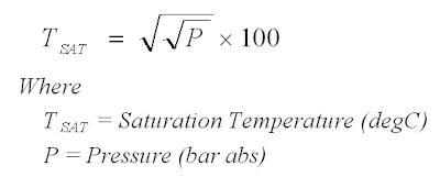
Quick Determination of Steam Saturated Temperature (Tsat)

What is quick estimation of steam saturated temperature ?

Square-root-Square-root formula may be used. The formula is :


Monday, November 24, 2008

Relief Valve Standard API Effective Orifice Area

Relief Valve Standard API Effective Orifice Area
API has generated the standard API Effective Orifice Area with corresponding designation letter (following table). Besides, standard effective orifice area, it also has a series of corresponding inlet size, outlet size combination for various pressure classes of flanged relief valves. All these information are tabulated in API Std 526 Flanged Steel Pressure Relief Valves.


API Relief Valve Standard Effective Discharge Orifice Areas
Designationin2cm2
D0.1100.71
E0.1961.26
F0.3071.98
G0.5033.24
H0.7855.06
J1.2878.30
K1.83811.85
L2.85318.40
M3.60023.23
N4.34028.00
P6.38041.16
Q11.05071.29
R16.000103.22
T26.000167.74


Tuesday, November 18, 2008

HC Gas Heat capacity ratio (Approx.)

Heat capacity ratio (or Isentropic exponent, k) is the ratio of specific heat capacity at constant pressure (CP) to specific heat capacity at constant volume (CV). It is commonly used in critical pressure ratio estimation, compression head estimation, etc. Following is a approximate k factor of Hydrocarbon gases. It may be used when only HC gas molecular weight (MW) and temperature (T) is available.


Typical Efficiency for Compressor

Compressor efficiency is very much subject to compressor type, design, etc. It possibly range from 50% to 90%. Each compressor from different manufacturer may have different efficiency. Following are some typical compressor efficiency may be used during design phase. It shall be decided by compressor manufacturer.

Centrifugal : 75-80%
Note : nowadays several manufacturers may have some compressor efficiency upto 84%.

Centrifugal : 75-85%

Reciprocating :
- 65% with Compression ratio of 1.5
- 75% with Compression ratio of 2.0
- 80-85% with Compression ratio of 3-6

Rotary : 70%

Other Interesting Articles

Saturday, November 1, 2008

Why CO2 with present of water is corrosive ?

Carbon dioxide (chemical formula: CO2 ) is a chemical compound composed of two oxygen atoms covalently bonded to a single carbon atom. It is a gas at standard temperature and pressure and present in oil and gas fluid. CO2 by itself is not corrosive, however, with the present of free water (H2O), it becomes corrosive and poses a thread to many oil and gas facilities.

CO2 with present of free water would lead to generation of Carbonic acid (H2CO3).

CO2 + H2O ==> H2CO3 ==> H+ + HCO32-

When Carbonic Acid contact with steel (Fe), reaction occur.

2Fe + H2CO3 ==> Fe2CO3 + H2

With minimum level of Oxygen would aggregate the corrosion :
Corrosion without Acid Carbonic :

4Fe + 3O2 + 6H2O ==> 4Fe(OH)3

and Corrosion with Acid Carbonic :

Fe + 2H2CO3 ==> Fe(HCO3)2 + H2

2Fe(HCO3)2 + 1/2 O2 ==> Fe2O3 + 4CO2 + 2H2O

Carbonic acid is weak acid would reduce the pH of fluid and this further aggregate the corrosion.

Other Interesting Article

Thursday, October 30, 2008

Relationship Between MOP & MAOP

Maximum Operating Pressure (MOP)
A maximum pressure at any expected normal operating scenario.

Maximum Allowable Operating Pressure (MAOP)
A maximum pressure that allowable by any equipment and device to operate satisfactory without affecting it performance. Example, a conventional direct spring loaded pressure relief valve allow MOP is 90% of set pressure whilst a pilot operated pressure relief valve may allow upto 97-98% of set pressure.

For Design Pressure & MAWP, read in "Relationship Between Design Pressure & Maximum Allowable Working Pressure (MAWP)".

MOP <= MAOP < Design Pressure <= MAWP

Other Interesting Articles

Sunday, October 26, 2008

Determine Interstage Pressure for Multi-stages Centrifugal Compressor

How to determine interstage pressure for multi-stages centrifugal compressor ?

For a n-stages centrifugal compressor system with inlet and outlet pressure of P0 and Pn, the compression ratio (r) should be about the same in each stage.

r = (Pn/P0)(1/n)

P1 = r.P0
P2 = r.P1
P3 = r.P2
.
.
.
Pn = r.Pn-1


Pressure Head Increases for Fan and Blower

What is pressure head increases for a fan and/or a blower ?


Fans are used to increase pressure head by about 3%, 12" water (300mm H2O)

Blowers are used to increase pressure head to lower than 2.75 barg (40 psig)

Monday, October 20, 2008

Relationship Between Design Pressure & Maximum Allowable Working Pressure (MAWP)

Maximum Allowable Working Pressure (MAWP)
Maximum gauge pressure permissible at the top of a completed vessel in its normal operating position at the designated coincident temperature specified for that pressure. MAWP is the least of the values for the internal or external pressure as determined by the vessel design rules for each element of the vessel using actual nominal thickness, exclusive of additional metal thickness allowed for corrosion and loadings other than pressure. The MAWP is the basis for the pressure setting of the pressure-relief devices that protect the vessel.

Design pressure
A pressure with coincident design temperature, used to determine the minimum permissible thickness or physical characteristic of each component, as determined by the design rules of the pressure-design code. The design pressure is selected by the designer to provide a suitable margin above the most severe pressure expected during normal operation at a coincident temperature. The design pressure is equal to or less than the Maximum Allowable Working Pressure (MAWP).


Design Pressure <= MAWP


Note :
Design pressure is normally the Pressure Relief Valve (RV) set pressure of a vessel. This pressure at coincident temperature is used to determine the minimum wall thickness. A calculated thickness is 9 mm based on a design pressure @ coincident temperature. However, with a standard material thickness of 10 mm. The MAWP would be calculated pressure based on this thickness.

Saturday, October 11, 2008

Absolute & Relative Roughness for Piping Material

What is absolute & Relative roughness for piping material ?

Pipe absolute roughness
Pipe absolute roughness (e) tabulated are taken from from several sources. These values are for new pipes and typically for new design purpose. For aged pipes or debottlenecking purpose, higher roughness are expected.

Piping Material
Absolute roughness
(Micron)
Source
drawn brass
1.5(1,2)
drawn copper
1.5(1,2)
commercial steel
45
(1,2)
wrought iron
45
(1,2)
asphalted cast iron120
(1,2)
galvanized iron150
(1,2)
cast iron260
(1,2)
wood stave
200 to 900
(1,2)
concrete
300 to 3000
(1,2)
riveted steel900 to 9000(1,2)
Rubber (smooth)6 to 70(3)
Rubber (wire-reinforce)300 to 4000(3)
Stainless Steel
/ Titanium
/ Cu-Ni
45.7(4)
Carbon steel (CS)
non-corroded - General
45.7(4)
Carbon steel (CS)
non-corroded - Relief system
150 (4)
Carbon steel (CS) corroded 457(4)
Fiberglass5(5)
PVC 1.5(6)
Copper1.5(6)
Aluminum1.5(6)
RedBrass1.5(6)


* 1m = 1,000 mm = 1,000,000 micron ; 1 mm = 1,000 micron

Pipe Relative roughness
Relative pipe roughness is the ratio of absolute roughness (e) by and pipe diameter (D) :

Relative Pipe Roughness = e/D


(1) Binder, R.C. (1973), Fluid Mechanics, Prentice-Hall, Inc. (Englewood Cliffs, NJ).
(2) GPSA & Crane Technical Paper No. 410M
(3) Darby, R. (2001), Fluid Mechanics for Chemical Engineers, Vol 2, Marcel Dekker, (NY)
(4) BP GP 44-80
(5) Fiberglass Pipe Handbook, SPI Composites Institute
(6) Enginereed Software’s PIPE-FLO software www.engineered-software.com

Thursday, October 9, 2008

What is event scheduler in HYSYS Dynamic simulation ?

What is event scheduler in HYSYS Dynamic simulation ?


Event scheduler is a useful tool for Dynamic simulation in HYSYS. It helps you to schedule your event in dynamic simulation. Dynamic simulation normally helps engineer to simulate different scenario (especially upset scenario) and testing functionality of control logic, etc.

For example, to simulate the start up of the plant, In the beginning, you need to open Valve-1, then 1 hr later, you need to close Valve-1, and start compressor and open Valve-2. These activities in sequence can be carried out manually when our integrator reaches our expected time. On the other hand, we may automate these activities using event scheduler in order to simplify work.

The structure of event scheduler in HYSYS as follow :

Schedule-->Sequence--->Event--->Action

Action is final layer to help us to do our expected work, such as specify variable, set controller mode etc. You should also specify the condition to do the action, such as elapsed time or even logic.

Tuesday, October 7, 2008

Pyrophoric Fire

"Pyrophoric" material is any material can be ignited or burned spontaneously in air when it is scratched, or struck, cracked, etc.

Typical component is Sulfur in Carbon steel vessel. Ferum (Fe) in carbon steel vessel reacts with Sulfur present in fluid and formed iron sulfide (FeS) which is a pyrophoric material that oxidizes exothermically when exposed to air.

Refinery, LNG production and gas treatment plant may expose to sulfur. Iron sulfide scale may appeared in Carbon steel vessel. It is typically a conversion of iron oxide, Fe2O3 (rust) to iron sulfide (FeS) in an oxygen-free atmosphere where hydrogen sulfide gas is present.

In Oxygen-free environment (during normal operation) :
Fe2O3 + 3H2S ==> 2FeS + 3H2O + S

When expose to Oxygen (during maintenance) :
FeS + 3O2 ==> 2Fe2O3 + 4S + Heat
FeS + 7O2 ==> 2Fe2O3 + 4SO2 + Heat

Heat is dissipated quickly and white smoke of SO2 gas released and followed by pyrophoric fires. This process is quick and exothermic oxidation.

Saturday, October 4, 2008

Wobbe Index

Wobbe Index (WI) is used to compare the combustion energy output of different composition fuel gases. Wobbe index is used to define interchangeability of fuel. Two fuels with identical Wobbe Index at given pressure and valve setting (orifice size), the energy output will be identical. The variation in WI is typically upto 5% (but maximum could be 10% for some manufacturer).

Wobbe Index (WI) is define as

WI = HHV / Sqrt (SG)

where
Sqrt = Square root of
HHV = High Heating Value (Btu/Scf)*
SG = Specific Gravity (MWgas / 28.96)

* Some may use Lower Heating Value to define WI


Other Interesting Article :
i)
Conversion from Weight Fraction to Mole Fraction
ii)Unit Conversion in Energy in LNG Sector

Gas liquid Separator Sizing Using GPSA (11ed)

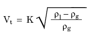
A gas liquid separator is used for bulk separation and mist eliminator i.e. vane type, mesh type, cyclone type) are used to promote liquid drop coalescence and separation from gas. Souder-Brown equation has been widely used in Oil and gas industry to size a gas liquid separator with and without mist eliminator.


where

ρl = Liquid density, kg/m3 (or lb/ft3)
ρg = Vapor density, kg/m3 (or lb/ft3)

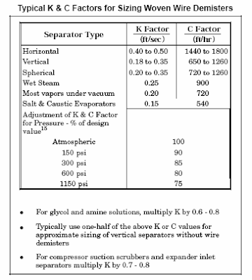
Generally the K factor as proposed in GPSA 11ed has been used by many engineers. Following figure tabulate the K factor may be used for horizontal, vertical, vertical scrubber and others separator for special services.

Wednesday, October 1, 2008

Why Droplet Still Fall at Terminal Velocity ?

Force balance Equation for terminal velocity of a freely falling droplet or particle

Force balance : Drag force + Buoyancy force = Gravity force

Lets take the case of freely falling droplet in a gas liquid separator, gas is flowing upwards and droplet is falling down now my, fundamental doubt is

  1. When all the force acting on the droplet get balanced (cancel out together), how the droplet can still fall ?
  2. Terminal velocity by definition is relative velocity of gas and droplet ?


A metal ball is held and once release in the air...

FORCE BALANCE
Drag force + Buoyancy force + External force + Gravity force = 0
Upward direction, Fd + Fb + Fe +(-Fg) = 0
==> Fd + Fb + Fe = Fg

Event at 0- second...
When the ball is at static condition (metal ball is held),
==> Fd is function of velocity and . As velocity is zero ==> Fd = 0
==> Fb is function of relative density between ambient and ball. Ball density (say metal ball is approx. 3000 kg/m3) relative to air (~1.3 kg/m3), it is almost negligible. ==> Fb=0

==> Thus, Fe= Fg, V=0 m/s


Event at 0+ second...
When the ball is just released (o+ second),
==> Fe = 0
==> Fb negligible. ==> Fb=0
==> Fg maintain with no change
==> Fd is function begin to increasing...

Net Force (Fg > Fd) will drive the ball downward. Ball velocity begin to increase.


Event at t second...
When the ball velocity increase upto terminal velocity (relative velocity between ball and gas),
==> Fe = 0
==> Fb negligible. ==> Fb=0
==> Fg maintain with no change
==> Fd increase upto terminal velocity

Terminal velocity
Ball velocity is increased upto a velocity where Fg = Fd, this velocity is called terminal velocity. At this velocity, net force = 0 as Fd = Fg ==> No further increase in velocity. Constant velocity.

Metal ball vs Droplet
Ball as compare to droplet, same principle applied. The differences area the droplet shape may change from time to time and drag coefficient (Cd) will change from time to time. From engineering perspective, the change (too small) is negligible.

Reference :
i) Gas liquid Separator Sizing Using GPSA
ii) Two Suction Nozzles on Drum for Two Pumps Operation...

Tuesday, September 30, 2008

How to Set Hot Pump Non-return Valve bypass Flowrate ?

Can someone suggest the flow rate through the Restriction Orifice (RO) on a pump warm-up bypass line for the standby pump, maybe a certain percentage of the rated flow of the running pump ?

Above question could be tackled in simple or difficult way. However lets start to understand the purpose, how it is implemented and how to set the flow.

Purpose
The main purpose of the bypass line is to maintain a minimum temperature different between the pump (and associate piping ) and the pump suction fluid temperature to avoid temperature shock in the event of standby pump is started-up automatically.

How it is implemented ?
The bypass can be a fixed RO, non-return valve with hole or a globe valve. It generally install across the standby pump discharge non-return valve.

How much flow ?
The bypass flow rate should be sufficient to cater for :

i) pump and associate piping heat-up from minimum ambient to normal suction temperature within a reasonable time i.e. 2 hours
ii) heat leakage via insulation during normal operation

Generally above calculation are time consuming.

Tips
Experience based approach may be taken where setting the RO / NRV hole size as 6-8 mm or install a one (1) in globe valve.

Reference :
i) Why bypass Non-Return Valve (NRV) ?

Monday, September 29, 2008

Do i Normally Calculate Thermal Relief Load ?

Authority reserve the right to ask for calculation for thermal relief. If you or your company have done sufficient research and can be submitted to authority as supporting document, then don't waste your time to calculate it. Otherwise, you better get ready when authority ask for it...

In many event, a simple and smallest PSV i.e. DN 20 × DN 25 (NPS ¾ × NPS 1) would be sufficient for thermal relief.

Somehow if there is doubt the provided PSV is not adequate, it shall be calculated according to using Hydraulic expansion method may be used.

If the liquid being relieved potentially flash or form solids while it passes through the PSV, hydraulic expansion with two phase relief method may be used. Details refer to :
  • J. C. LEUNG, "Size Safety Relief Valves for Flashing Liquids", Chemical Engineering Progress, February 1992, pp. 70-75
  • J. C. LEUNG, and F. N. NAZARIO, "Two-Phase Flashing Flow Methods and Comparison", Journal of Loss Prevention Process Industries, Volume 3, Number 2, 1990, pp. 253-260
  • L. L. SIMPSON, "Estimate Two-Phase Flow in Safety Devices", Chemical Engineering, August 1991, pp. 98-102
Reference :
i) API Std 521 section 5.14.2., 5.14.3
ii) Thermal Relief of Non-Flashing Liquid in Pipe
iii) When Do i need a PSV for Thermal Relief on Piping ?
iv) Simple Flow Chart to Determine Requirement of Thermal Relief

When Do i need a PSV for Thermal Relief on Piping ?

Generally PSV not required for piping... however...API STD 521 2007 Addendum May 2008, section 5.14.1 (c) stated that hydraulic expansion due to solar heating on "long pipelines" shall be assessed and checked if a pressure relief valve (PSV) is required. What is "long pipelines" ? Difficult...

This section allows that a PSV may not required for thermal relief if proper administrative procedures and addition of signs stipulating the proper venting and draining procedures when shut-down and block-in are implemented. These action are acceptable and considered do not compromise the safety of personnel or equipment.

System under consideration for thermal relief consists of piping only (does not contain pressure vessels or heat exchangers), a pressure-relief device might not be required to protect piping from thermal expansion if :

  1. piping is always contains a pocket of non-condensing vapour, such that it can never become liquid-full (even it is heated and compressed); OR
  2. piping is in continuous use (i.e., not batch or semi-continuous use) and drained after being blocked-in using well supervised procedures or permits; OR
  3. fluid temperature is greater than the maximum temperature expected from solar heating (the pipe temperature direct under solar heating can reached approximately 60 °C to 70 °C, it can be as high as 85 °C for certain area i.e. Middle east) and there are no other heat sources such as heat tracing; OR
  4. the estimated pressure rise from thermal expansion is within the design limits of the equipment or piping.

Saturday, September 27, 2008

Conversion from Weight Fraction to Mole Fraction

A mixture consist of n component, e1, e2, e3,...en with molecular weight MW1, MW2, MW3, ... MWn. Each component mass are M1, M2, M3, ... Mn.

MASS FRACTION
Mass fraction of component-1, X1 = M1/MT [Eq. 1-1]
Mass fraction of component-2, X2 = M2/MT [Eq. 1-2]
Mass fraction of component-3, X3 = M3/MT [Eq. 1-3]
.
.
Mass fraction of component-i, Xi = Mi/MT [Eq. 1-i]
.
.
.
Mass fraction of component-n, Xn = Mn/MT [Eq. 1-n]
.

Total mass in mixtures, MT = M1 + M2 + M3 +...+ Mn [Eq. 2]

Number of MOLE
Component-1 number of mole, N1 = M1/MW1 [Eq. 3-1]
Component-2 number of mole, N2 = M2/MW2 [Eq. 3-2]
Component-3 number of mole, N3 = M3/MW3 [Eq. 3-3]
.
.
Component-n number of mole, Nn = Mn/MWn [Eq. 3-n]

Total number of mole,
NT = N1 + N2 + N3 +...+ Nn [Eq. 4]
NT = [M1/MW1 + M2/MW2 + M3/MW3 +...+ Mn/MWn] [Eq. 5]

MOLE FRACTION
For component-1,

Y1 = N1 / NT
Y1 = (M1/MW1) / NT

From [Eq. 1-1],
X1 = M1/MT
M1 = X1* MT
Y1 = (X1*MT/MW1) / NT

Mole Fraction of component-1,
Y1 = (M1/MW1) / NT [Eq. 6-1a]
Y1 = (X1*MT/MW1) / NT [Eq. 6-1b]

Mole Fraction of component-2,
Y2 = (M2/MW2) / NT [Eq. 6-2a]
Y2 = (X2*MT/MW2) / NT [Eq. 6-2b]

Mole Fraction of component-3,
Y3 = (M3/MW3) / NT [Eq. 6-3b]
Y3 = (X3*MT/MW3) / NT [Eq. 6-3b]
.
.
.

Mole Fraction of component-n,
Yn = (Mn/MWn) / NT [Eq. 6-na]
Yn = (Xn*MT/MWn) / NT [Eq. 6-nb]