Showing posts with label PSV. Show all posts

Monday, November 24, 2008

Relief Valve Standard API Effective Orifice Area

Relief Valve Standard API Effective Orifice Area
API has generated the standard API Effective Orifice Area with corresponding designation letter (following table). Besides, standard effective orifice area, it also has a series of corresponding inlet size, outlet size combination for various pressure classes of flanged relief valves. All these information are tabulated in API Std 526 Flanged Steel Pressure Relief Valves.


API Relief Valve Standard Effective Discharge Orifice Areas
Designationin2cm2
D0.1100.71
E0.1961.26
F0.3071.98
G0.5033.24
H0.7855.06
J1.2878.30
K1.83811.85
L2.85318.40
M3.60023.23
N4.34028.00
P6.38041.16
Q11.05071.29
R16.000103.22
T26.000167.74


Monday, October 20, 2008

Relationship Between Design Pressure & Maximum Allowable Working Pressure (MAWP)

Maximum Allowable Working Pressure (MAWP)
Maximum gauge pressure permissible at the top of a completed vessel in its normal operating position at the designated coincident temperature specified for that pressure. MAWP is the least of the values for the internal or external pressure as determined by the vessel design rules for each element of the vessel using actual nominal thickness, exclusive of additional metal thickness allowed for corrosion and loadings other than pressure. The MAWP is the basis for the pressure setting of the pressure-relief devices that protect the vessel.

Design pressure
A pressure with coincident design temperature, used to determine the minimum permissible thickness or physical characteristic of each component, as determined by the design rules of the pressure-design code. The design pressure is selected by the designer to provide a suitable margin above the most severe pressure expected during normal operation at a coincident temperature. The design pressure is equal to or less than the Maximum Allowable Working Pressure (MAWP).


Design Pressure <= MAWP


Note :
Design pressure is normally the Pressure Relief Valve (RV) set pressure of a vessel. This pressure at coincident temperature is used to determine the minimum wall thickness. A calculated thickness is 9 mm based on a design pressure @ coincident temperature. However, with a standard material thickness of 10 mm. The MAWP would be calculated pressure based on this thickness.

Monday, September 29, 2008

Do i Normally Calculate Thermal Relief Load ?

Authority reserve the right to ask for calculation for thermal relief. If you or your company have done sufficient research and can be submitted to authority as supporting document, then don't waste your time to calculate it. Otherwise, you better get ready when authority ask for it...

In many event, a simple and smallest PSV i.e. DN 20 × DN 25 (NPS ¾ × NPS 1) would be sufficient for thermal relief.

Somehow if there is doubt the provided PSV is not adequate, it shall be calculated according to using Hydraulic expansion method may be used.

If the liquid being relieved potentially flash or form solids while it passes through the PSV, hydraulic expansion with two phase relief method may be used. Details refer to :
  • J. C. LEUNG, "Size Safety Relief Valves for Flashing Liquids", Chemical Engineering Progress, February 1992, pp. 70-75
  • J. C. LEUNG, and F. N. NAZARIO, "Two-Phase Flashing Flow Methods and Comparison", Journal of Loss Prevention Process Industries, Volume 3, Number 2, 1990, pp. 253-260
  • L. L. SIMPSON, "Estimate Two-Phase Flow in Safety Devices", Chemical Engineering, August 1991, pp. 98-102
Reference :
i) API Std 521 section 5.14.2., 5.14.3
ii) Thermal Relief of Non-Flashing Liquid in Pipe
iii) When Do i need a PSV for Thermal Relief on Piping ?
iv) Simple Flow Chart to Determine Requirement of Thermal Relief

When Do i need a PSV for Thermal Relief on Piping ?

Generally PSV not required for piping... however...API STD 521 2007 Addendum May 2008, section 5.14.1 (c) stated that hydraulic expansion due to solar heating on "long pipelines" shall be assessed and checked if a pressure relief valve (PSV) is required. What is "long pipelines" ? Difficult...

This section allows that a PSV may not required for thermal relief if proper administrative procedures and addition of signs stipulating the proper venting and draining procedures when shut-down and block-in are implemented. These action are acceptable and considered do not compromise the safety of personnel or equipment.

System under consideration for thermal relief consists of piping only (does not contain pressure vessels or heat exchangers), a pressure-relief device might not be required to protect piping from thermal expansion if :

  1. piping is always contains a pocket of non-condensing vapour, such that it can never become liquid-full (even it is heated and compressed); OR
  2. piping is in continuous use (i.e., not batch or semi-continuous use) and drained after being blocked-in using well supervised procedures or permits; OR
  3. fluid temperature is greater than the maximum temperature expected from solar heating (the pipe temperature direct under solar heating can reached approximately 60 °C to 70 °C, it can be as high as 85 °C for certain area i.e. Middle east) and there are no other heat sources such as heat tracing; OR
  4. the estimated pressure rise from thermal expansion is within the design limits of the equipment or piping.

Wednesday, September 24, 2008

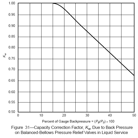
PSV Capacity Correction Factor (Kw) Due to Back Pressure in Liquid Service

Capacity Correction Factor (Kw) Due to Back Pressure in Liquid Service

Conventional & Pilot Operated Pressure Relief Valves

- No special correction.

Balanced-Bellows Pressure Relief Valves

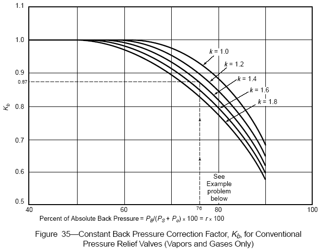
PSV Constant Back Pressure Correction Factor (Kb) for Vapor & Gas

Constant Back Pressure Correction Factor (Kb)

For Conventional Pressure Relief Valves (Vapors and Gases Only)


Note: This chart is typical and suitable for use only when the make of the valve or the actual critical flow pressure point for the vapor or gas is unknown; otherwise, the valve manufacturer should be consulted for specific data. This correction factor should be used only in the sizing of conventional (nonbalanced) pressure relief valves that have their spring setting adjusted to compensate for the superimposed back pressure. It should not be used to size balanced-type valves.


For Balanced-Bellows Pressure Relief Valve (Vapors and Gases Only)


Notes:
1. The curves above represent a compromise of the values recommended by a number of relief valve manufacturers and may be used when the make of the valve or the critical flow pressure point for the vapor or gas is unknown. When the make of the valve is known, the manufacturer should be consulted for the correction factor. These curves are for set pressures of 50 psig and above. They are limited to back pressure below critical flow pressure for a given set pressure. For set pressures below 50 psig or for subcritical flow, the manufacturer must be consulted for values of Kb.

2. See paragraph 3.3.3. in API Rp 520 Part 1

3. For 21% overpressure, Kb equals 1.0 up to PB/PS = 50%.


Related Articles

What is Capacity Correction Factor (CCF) due to Back pressure for PSV ?

What is capacity correction factor, Kb in orifice area calculation in PSV. How do we calculate this value ?

* PSV - Pressure Relief Valve

Back pressure will tend to produce a closing force on the unbalanced portion of the disc. This force may result in a reduction in lift and an associated reduction in flow capacity. Capacity correction factors, called back pressure correction factors, are provided by manufacturers to account for this reduction in flow.

For preliminary PSV sizing, figures in API RP 520 Part 1 can be referred.

Reference :
i) API RP 520 Part 1

Related Articles