Thursday, October 30, 2008

Relationship Between MOP & MAOP

Maximum Operating Pressure (MOP)
A maximum pressure at any expected normal operating scenario.

Maximum Allowable Operating Pressure (MAOP)
A maximum pressure that allowable by any equipment and device to operate satisfactory without affecting it performance. Example, a conventional direct spring loaded pressure relief valve allow MOP is 90% of set pressure whilst a pilot operated pressure relief valve may allow upto 97-98% of set pressure.

For Design Pressure & MAWP, read in "Relationship Between Design Pressure & Maximum Allowable Working Pressure (MAWP)".

MOP <= MAOP < Design Pressure <= MAWP

Other Interesting Articles

Sunday, October 26, 2008

Determine Interstage Pressure for Multi-stages Centrifugal Compressor

How to determine interstage pressure for multi-stages centrifugal compressor ?

For a n-stages centrifugal compressor system with inlet and outlet pressure of P0 and Pn, the compression ratio (r) should be about the same in each stage.

r = (Pn/P0)(1/n)

P1 = r.P0
P2 = r.P1
P3 = r.P2
.
.
.
Pn = r.Pn-1


Pressure Head Increases for Fan and Blower

What is pressure head increases for a fan and/or a blower ?


Fans are used to increase pressure head by about 3%, 12" water (300mm H2O)

Blowers are used to increase pressure head to lower than 2.75 barg (40 psig)

Monday, October 20, 2008

Relationship Between Design Pressure & Maximum Allowable Working Pressure (MAWP)

Maximum Allowable Working Pressure (MAWP)
Maximum gauge pressure permissible at the top of a completed vessel in its normal operating position at the designated coincident temperature specified for that pressure. MAWP is the least of the values for the internal or external pressure as determined by the vessel design rules for each element of the vessel using actual nominal thickness, exclusive of additional metal thickness allowed for corrosion and loadings other than pressure. The MAWP is the basis for the pressure setting of the pressure-relief devices that protect the vessel.

Design pressure
A pressure with coincident design temperature, used to determine the minimum permissible thickness or physical characteristic of each component, as determined by the design rules of the pressure-design code. The design pressure is selected by the designer to provide a suitable margin above the most severe pressure expected during normal operation at a coincident temperature. The design pressure is equal to or less than the Maximum Allowable Working Pressure (MAWP).


Design Pressure <= MAWP


Note :
Design pressure is normally the Pressure Relief Valve (RV) set pressure of a vessel. This pressure at coincident temperature is used to determine the minimum wall thickness. A calculated thickness is 9 mm based on a design pressure @ coincident temperature. However, with a standard material thickness of 10 mm. The MAWP would be calculated pressure based on this thickness.

Saturday, October 11, 2008

Absolute & Relative Roughness for Piping Material

What is absolute & Relative roughness for piping material ?

Pipe absolute roughness
Pipe absolute roughness (e) tabulated are taken from from several sources. These values are for new pipes and typically for new design purpose. For aged pipes or debottlenecking purpose, higher roughness are expected.

Piping Material
Absolute roughness
(Micron)
Source
drawn brass
1.5(1,2)
drawn copper
1.5(1,2)
commercial steel
45
(1,2)
wrought iron
45
(1,2)
asphalted cast iron120
(1,2)
galvanized iron150
(1,2)
cast iron260
(1,2)
wood stave
200 to 900
(1,2)
concrete
300 to 3000
(1,2)
riveted steel900 to 9000(1,2)
Rubber (smooth)6 to 70(3)
Rubber (wire-reinforce)300 to 4000(3)
Stainless Steel
/ Titanium
/ Cu-Ni
45.7(4)
Carbon steel (CS)
non-corroded - General
45.7(4)
Carbon steel (CS)
non-corroded - Relief system
150 (4)
Carbon steel (CS) corroded 457(4)
Fiberglass5(5)
PVC 1.5(6)
Copper1.5(6)
Aluminum1.5(6)
RedBrass1.5(6)


* 1m = 1,000 mm = 1,000,000 micron ; 1 mm = 1,000 micron

Pipe Relative roughness
Relative pipe roughness is the ratio of absolute roughness (e) by and pipe diameter (D) :

Relative Pipe Roughness = e/D


(1) Binder, R.C. (1973), Fluid Mechanics, Prentice-Hall, Inc. (Englewood Cliffs, NJ).
(2) GPSA & Crane Technical Paper No. 410M
(3) Darby, R. (2001), Fluid Mechanics for Chemical Engineers, Vol 2, Marcel Dekker, (NY)
(4) BP GP 44-80
(5) Fiberglass Pipe Handbook, SPI Composites Institute
(6) Enginereed Software’s PIPE-FLO software www.engineered-software.com

Thursday, October 9, 2008

What is event scheduler in HYSYS Dynamic simulation ?

What is event scheduler in HYSYS Dynamic simulation ?


Event scheduler is a useful tool for Dynamic simulation in HYSYS. It helps you to schedule your event in dynamic simulation. Dynamic simulation normally helps engineer to simulate different scenario (especially upset scenario) and testing functionality of control logic, etc.

For example, to simulate the start up of the plant, In the beginning, you need to open Valve-1, then 1 hr later, you need to close Valve-1, and start compressor and open Valve-2. These activities in sequence can be carried out manually when our integrator reaches our expected time. On the other hand, we may automate these activities using event scheduler in order to simplify work.

The structure of event scheduler in HYSYS as follow :

Schedule-->Sequence--->Event--->Action

Action is final layer to help us to do our expected work, such as specify variable, set controller mode etc. You should also specify the condition to do the action, such as elapsed time or even logic.

Tuesday, October 7, 2008

Pyrophoric Fire

"Pyrophoric" material is any material can be ignited or burned spontaneously in air when it is scratched, or struck, cracked, etc.

Typical component is Sulfur in Carbon steel vessel. Ferum (Fe) in carbon steel vessel reacts with Sulfur present in fluid and formed iron sulfide (FeS) which is a pyrophoric material that oxidizes exothermically when exposed to air.

Refinery, LNG production and gas treatment plant may expose to sulfur. Iron sulfide scale may appeared in Carbon steel vessel. It is typically a conversion of iron oxide, Fe2O3 (rust) to iron sulfide (FeS) in an oxygen-free atmosphere where hydrogen sulfide gas is present.

In Oxygen-free environment (during normal operation) :
Fe2O3 + 3H2S ==> 2FeS + 3H2O + S

When expose to Oxygen (during maintenance) :
FeS + 3O2 ==> 2Fe2O3 + 4S + Heat
FeS + 7O2 ==> 2Fe2O3 + 4SO2 + Heat

Heat is dissipated quickly and white smoke of SO2 gas released and followed by pyrophoric fires. This process is quick and exothermic oxidation.

Saturday, October 4, 2008

Wobbe Index

Wobbe Index (WI) is used to compare the combustion energy output of different composition fuel gases. Wobbe index is used to define interchangeability of fuel. Two fuels with identical Wobbe Index at given pressure and valve setting (orifice size), the energy output will be identical. The variation in WI is typically upto 5% (but maximum could be 10% for some manufacturer).

Wobbe Index (WI) is define as

WI = HHV / Sqrt (SG)

where
Sqrt = Square root of
HHV = High Heating Value (Btu/Scf)*
SG = Specific Gravity (MWgas / 28.96)

* Some may use Lower Heating Value to define WI


Other Interesting Article :
i)
Conversion from Weight Fraction to Mole Fraction
ii)Unit Conversion in Energy in LNG Sector

Gas liquid Separator Sizing Using GPSA (11ed)

A gas liquid separator is used for bulk separation and mist eliminator i.e. vane type, mesh type, cyclone type) are used to promote liquid drop coalescence and separation from gas. Souder-Brown equation has been widely used in Oil and gas industry to size a gas liquid separator with and without mist eliminator.


where

ρl = Liquid density, kg/m3 (or lb/ft3)
ρg = Vapor density, kg/m3 (or lb/ft3)

Generally the K factor as proposed in GPSA 11ed has been used by many engineers. Following figure tabulate the K factor may be used for horizontal, vertical, vertical scrubber and others separator for special services.

Wednesday, October 1, 2008

Why Droplet Still Fall at Terminal Velocity ?

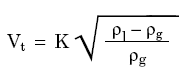
Force balance Equation for terminal velocity of a freely falling droplet or particle

Force balance : Drag force + Buoyancy force = Gravity force

Lets take the case of freely falling droplet in a gas liquid separator, gas is flowing upwards and droplet is falling down now my, fundamental doubt is

  1. When all the force acting on the droplet get balanced (cancel out together), how the droplet can still fall ?
  2. Terminal velocity by definition is relative velocity of gas and droplet ?


A metal ball is held and once release in the air...

FORCE BALANCE
Drag force + Buoyancy force + External force + Gravity force = 0
Upward direction, Fd + Fb + Fe +(-Fg) = 0
==> Fd + Fb + Fe = Fg

Event at 0- second...
When the ball is at static condition (metal ball is held),
==> Fd is function of velocity and . As velocity is zero ==> Fd = 0
==> Fb is function of relative density between ambient and ball. Ball density (say metal ball is approx. 3000 kg/m3) relative to air (~1.3 kg/m3), it is almost negligible. ==> Fb=0

==> Thus, Fe= Fg, V=0 m/s


Event at 0+ second...
When the ball is just released (o+ second),
==> Fe = 0
==> Fb negligible. ==> Fb=0
==> Fg maintain with no change
==> Fd is function begin to increasing...

Net Force (Fg > Fd) will drive the ball downward. Ball velocity begin to increase.


Event at t second...
When the ball velocity increase upto terminal velocity (relative velocity between ball and gas),
==> Fe = 0
==> Fb negligible. ==> Fb=0
==> Fg maintain with no change
==> Fd increase upto terminal velocity

Terminal velocity
Ball velocity is increased upto a velocity where Fg = Fd, this velocity is called terminal velocity. At this velocity, net force = 0 as Fd = Fg ==> No further increase in velocity. Constant velocity.

Metal ball vs Droplet
Ball as compare to droplet, same principle applied. The differences area the droplet shape may change from time to time and drag coefficient (Cd) will change from time to time. From engineering perspective, the change (too small) is negligible.

Reference :
i) Gas liquid Separator Sizing Using GPSA
ii) Two Suction Nozzles on Drum for Two Pumps Operation...